


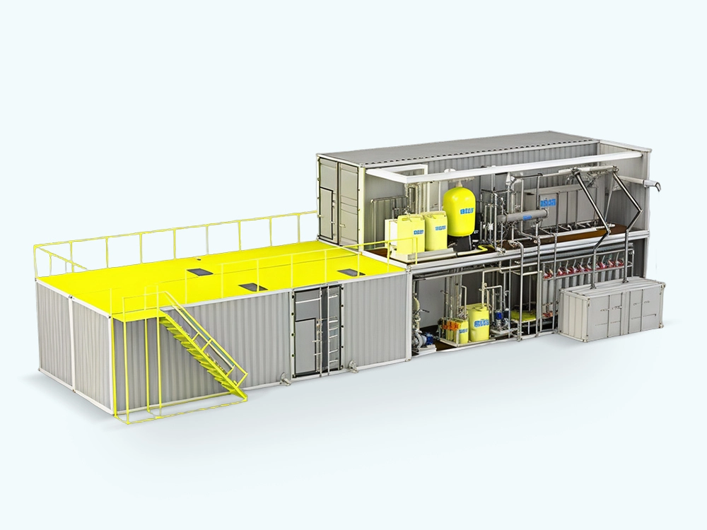
Containerised Dam Treatment System
● All Instrumentation and wiring materials within package
● Local Control Panels.
● Operating and Maintenance Manuals for our supplied package system
● Process design and system engineering
● Manufacturing, procurement and system performance
● Package Installation and commissioning
● Off-site training
Scope of Supply/Works by Others
(Not Limited to Mentioned Items)
● Access out of construction battery
● Site interconnection for multiple equipment.
● Incoming power supply from grid switch room / transformer
● Civil, Building and Plinth for Package system
● Building M&E
● Excavation outside our treatment plant battery limit
● Pipe, fittings, valves outside our treatment plant battery limit
● All QA/QC special test certificate for all equipment
● Horticulture, road, paving, carpark, street lights and any other landscaping additional requirement
● City water supply c/w piping to each location points
● Clean Dry Air (CDA) c/w piping and air regulator and air regulator to each location points.
NOTE: Not limited to above mentioned items
Design Basis
Construction Capacity
The construction capacity of packaged Containerised Integrated Water Treatment System designed as values shown in Table 2 below.
| Parameter | Value |
| Flow Rate | 216m3/hour |
| Operation Hour | 24 hours |
Remarks: Any deviation of above-mentioned parameter, may affect system design, quoted price and warranty.
*Note: Daily output is calculated based on 20 hours of operation.
Pocess Description
Compact Pre-Treatment
The Combined Pre-Treatment Plant consists of a screw screen, a decanting tank, a sand/grit extracting screw and a grease scraper. Sewage from civil or industrial waste water treatment plants has to be pre-treated before being transferred to any kind of purification system. The system carries out different processes: de-watering and compacting of screened solid waste, separation of sand/grit and removal of floating, greasy matter.
During the process solids, sand/grit and greasy matter present in the sewage are removed in order to avoid overloading of the downstream treatment system. Waste water enters the plant and is processed by means of separation by screw screen. Subsequently, a sedimentation process and the extraction of the sand or grit takes place. An additional degreasing device sees to the removal of fats and suspended solids using an aeration system and a special floating scraper.
Oxidation (EQ TANK)
In the aerated grit chamber, air is introduced along one side of tank to create a spiral flow pattern. The flow rate changes with the water flow rate and the air volume. Wastewater will move through the tank in a spiral path, where the heavier grit particles will settle to the bottom. Meanwhile, the organic matters covered on the surface of the sands are separated by aeration, resulting in the grit clean and easy to treat. The organic matters washed out from the grits could supplement the carbon source in the following biological system. In addition, the suspended matters are floated up and removed.
The main advantages of aerated grit chamber are:
Automatic Backwash Disc Fitler Pre-Treatment
Thin color-coded polypropylene discs are diagonally grooved on both sides to a specific micron size. A series of these discs is then stacked and compressed on a specially designed spine.
When it is stacked, the groove on top runs opposite to the groove below, creating a filtration element with a statistically significant series of groove and shoulder, which trap the solids. The stack is enclosed in a corrosion proof and pressure resistant housing.
During the filtration process, the filtration discs are tightly compressed together by the spring's power and the differential pressure, thus providing high filtration efficiency. Filtration occurs while water percolates from the outer diameter to the inner diameter of the element. Depending on the micron rating, there are 18 (in 400micron discs) to 32 (in 20-micron discs) stopping points in each track, thus creating the unique in-depth filtration.
Compact Automatic Disc Filter System
● Inlet water flows into the filter through the filter element
● The suspended solids in the water are trapped on and between the discs
● Filtered outlet water enters from the opposite direction through the outlet port of the filter.
● The flaps of the membrane are opened by the water pressure, allowing the water to flow only into the 3 flushing pipes.
● The water is forced through nozzles built into the flushing pipes.
● Water from the flushing pipes also flows into the piston and pushed the tightening cap up, decompressing the filtration element discs.
● Tangential jets of water cause fast spinning of the separated discs and remove the trapped solids.
● The solids are flushed from the filter to the drain.
Ultra Filtration (Uf) System
Ultrafiltration (UF) membranes are an excellent filtration technology for the treatment of surface and ground water to potable or process water standards and for effective effluent polishing. The hollow fibre membranes on the inside provide superior separation performance and effectively reject bacteria and viruses. Each module with a membrane surface area of 64m3 or 55m3 is installed vertically and connected directly to feed and filtrate headers.
Avangard Membrane ultrafiltration membranes an inside-out flow configuration with two modes of operation: dead end flow or recirculation flow. Recirculation flow is applied to increase the turbulence on the membrane surface. Both modes of operation are discontinuous with alternating filtration (production) and backwash (cleaning) steps. In the filtration step feed water is forced through the fibres, and in the backwash step some of the filtrate is forced back through the membranes to remove any solids. The inside-out configuration offers a high performance (flux/TMP) at a low energy and chemical consumption compare to outside-in where foot print is smaller.
Compact Ultra Filtration System
● Yields substantial savings in space, cost and energy
● Suited to build scalable systems
● Easy to integrate with other processes
● Provides a reliable single barrier for bacteria and viruses
● Low energy consumption
● Fully automated, no operator involvement
● Uses low-cost chemicals
● Minimal maintenance expenses
● Integrity testing
● No operator exposure to fumes or aerosols
● Small footprint
● High removal of organics
● Phosphate removal
Softening Nano Filtration (Nf) System
The AVANGARD MEMBRANE Nanofiltration membrane product is primarily used in the oil and gas industry. These membranes are high-performance nanofiltration membranes which are able to selectively remove Ions, thereby reducing the risks of scaling and reservoir souring when seawater is injected into the oil containing reservoirs for secondary oil production in offshore production. The membrane rejects 99.5% of ions while passing other ions, particularly monovalent ions such as chloride and sodium, allowing for low-pressure operations.
They use patented Low Differentially Pressure technology designed to minimize colloidal fouling. AVANGARD MEMBRANE use a 34-mil thickness feed spacer that prevents colloidal fouling and increases the effectiveness of membrane cleaning – resulting in lower differential pressure.
As a result, the AVANGARD MEMBRANE does not need to be cleaned frequently – thus reducing treatment cost – while offering extreme durability and consistent performance.
NANOFILTRATION is globally acclaimed for high ions rejection characteristics in oil and gas seawater injection applications. It significantly reduces operating costs and provides optimum hardness rejection in softening
applications.
| MgSO4 Permeate Flow (Nominal) | 11,000 gpd (41.6 m3/d) |
| MgSO4 Rejection | 99.8% (99.5% minimum) |
| Configuration | Spiral Wound |
| Membrane Polymer | Composite Polyamide |
| Nominal Membrane Area | 400 ft2 (37 m2) |
| Feed/Brine Spacer Thickness | 34 mil (0.87 mm) |
Operation Limit
● Maxium Applied Pressure (Recommended): 600 psig (4.14 MPa)
● Maximum Chlorine Concentration: < 0.1 PPM
● Maximum Operating Temperature: 113°F (45°C)
● pH Range, Operation (Cleaning): 3.0 - 9.0 (1.0 – 11.5)
● Maximum Feedwater Turbidity: 1.0 NTU
● Maximum Feedwater SDI (15 mins): 5.0
● Maximum Feed Flow: 75 GPM (17.0 m3/h)
● Maximum Pressure Drop for Each Element: 15 psi
● Typical Seawater Performance†:
● Nominal Permeate Flow: 6,500 gpd (24.6 m3/d)
● Nominal Chloride Rejection: 25%
● Nominal Sulfate Rejection: 97%
Ultra Violet (Uv) Disinfection
UV disinfection system is a closed-vessel, inline Ultraviolet (UV) reactor designed for pressurized pipe installation. This system provides instantaneous, chemical-free pathogen control for municipal water supply without the need for contact tanks or chemical storage.
As the treated water flow passes through the stainless-steel chamber, it is exposed to high-intensity UV-C light at a wavelength of 254 nm. This light penetrates the cells of microorganisms and permanently alters their DNA/RNA, rendering them incapable of reproduction and effectively disinfecting the water without the use of chemicals.
Advantage
Do You Have any Questions? Welcome to Leave Us a Message.
Tel: +86 13370035529
Business What's App: +86 13636655908
E-mail: qilee@qileegroup.com
Add: No. 351 Wenqu Road, Fengxian District, Shanghai